The Long Road From There to Here
In April 2025 I fired up my computer to have a good session with Star Citizen, as I do regularly — firing up my trusty Joystick Gremlin profile and launching into space. As is quite often the case in this game, my ship careened straight into the side of the hangar and exploded. Although in this particular case it was more to do with the fact that Up had become Down on the wrong side of my cockpit and I could no longer fly in a straight line.
There must be a better way, I thought to myself, and so I started a long journey to build a hardware version of this mapping software — one that does not rely on drivers, virtual joysticks, or hiding other HID devices from your computer. As an additional impetus, I had been considering for a number of months moving my gaming PC to Linux, and had been following closely the effort to run Star Citizen and similar games on that platform. One of the things that always stops me is that there's nothing to replace my trusty Gremlin and its related drivers.
And so I set out on my epic journey with nothing but my GCSE (nearly 40 years ago) knowledge of electronics, a thirst for learning, and some basic programming skills — which had mostly been around things like Python or C#. Or, if we're being honest, BBC BASIC and Pascal, LOL!
My first attempt was based on a Raspberry Pi running Linux. Surely I can get Linux to do this bit of Python and it'll be no problem at all, I thought. It was an interesting learning experience — I definitely learned the first chunk of how deep the USB rabbit hole is from this part of the project — but ultimately it was a failure.
After much wailing and gnashing of teeth, I eventually conceded that I was going to have to look at microcontrollers such as the ESP32, and so down the new rabbit hole I went.
With that decision made, I started to review my choices in the Arduino world, but quickly found that whilst I could get some way along the journey I needed to take, it was obvious I was going to have to move into the lower level of C programming in order to achieve what I wanted to do.
Having never done any C before, this was quite a deep rabbit hole to jump into. However, with the help of the internet and the then-early stages of AI, I started to learn what I needed to know, and came up with the architecture you see below. The two devices back to back I call, internally within the project, a Device Management and Emulation Unit — or DMEU for short — managed by a separate management unit that provides policy and administration.
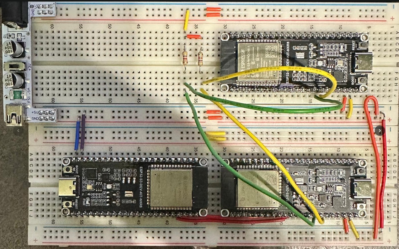
Having devised the structure, I set about — one rainy afternoon on the train to London — writing a full project plan, laying out that I wanted to be able to map axes, that I needed to support up to eight DMEUs, in a package the user should be able to administer without any additional drivers or software. In the early stages we used an I²C bus to communicate between the management and the modules.
The first hurdle was, of course, that I needed a flexible HID report-processing driver capable of taking any input device and mapping it to a predictable, understood output format. This took many months. I can't underestimate how much I had to learn about how USB — and the protocol that runs on top of it — works. Literal months were spent making tweaks to code, reviewing output, and understanding binary and hexadecimal descriptor files. If I'm honest, this was probably the most complicated part of the project overall, with the exception of the communication protocol.
Learning that I²C shouldn't be taking this long in the project, I set about trying to master its bus protocols — and soon discovered there were no large-file or large-data-structure transport libraries available for it. So I set about writing my own TCP-like protocol (for those who understand) to make the communication between the devices resilient.
I had already decided at this point that the DM-to-EU communication — an input HID device going to an output emulation unit — should be over serial, and that was done nice and fast and clean. But I needed the different units to be able to talk to each other and to the management.
After far too long sensibly trying to get this to work, I admitted defeat, turned to one of the now-ubiquitous AI systems, and gave it my problem: I have this type of data structure, I need this reliability, I need this speed of transit — I've tried I²C, I can't use serial, what should I do? In the usual casually-sensible way that AI seems to have adopted, it told me I should be using CAN bus.
Having prototyped this using a couple of plug-in transceivers — and smashing my head against the desk realising how easy it was going to be to use this new protocol — I then set about building a new, more stable prototype to continue development.
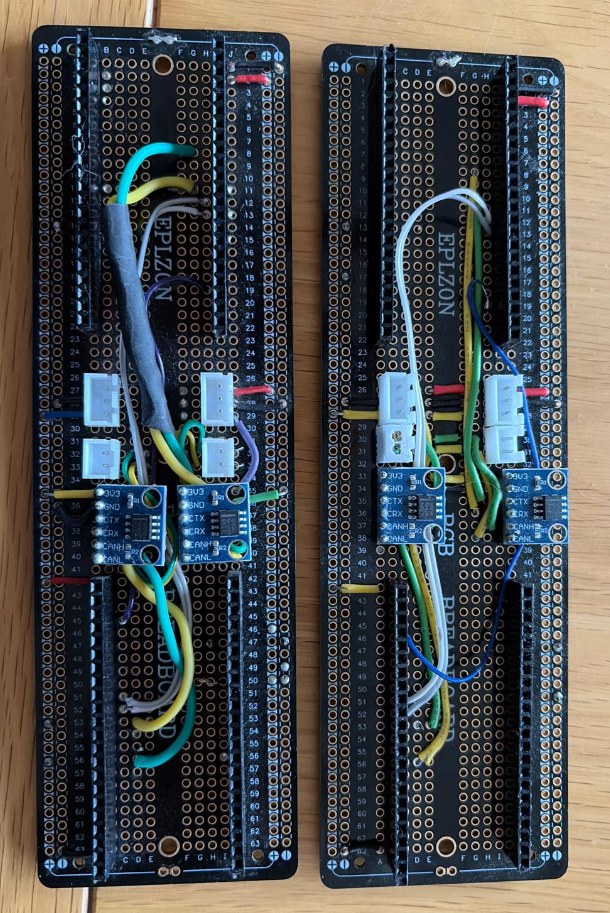
This turned out to be the trickle that broke the dam. Once the communication protocol between the units was working at a speed I found tolerable, I could set about creating the features I've always wanted to add to the project: the ability to map axes with scale curves and dead zones; the ability to have a button on one device affect a different output; an admin unit that could support a web front-end, and more.
After getting most of the key features in place, I then designed my first-ever PCB for manufacture — one that let me run the CAN bus at a full 1 Mbit in order to really push the system and make sure it was going to work.
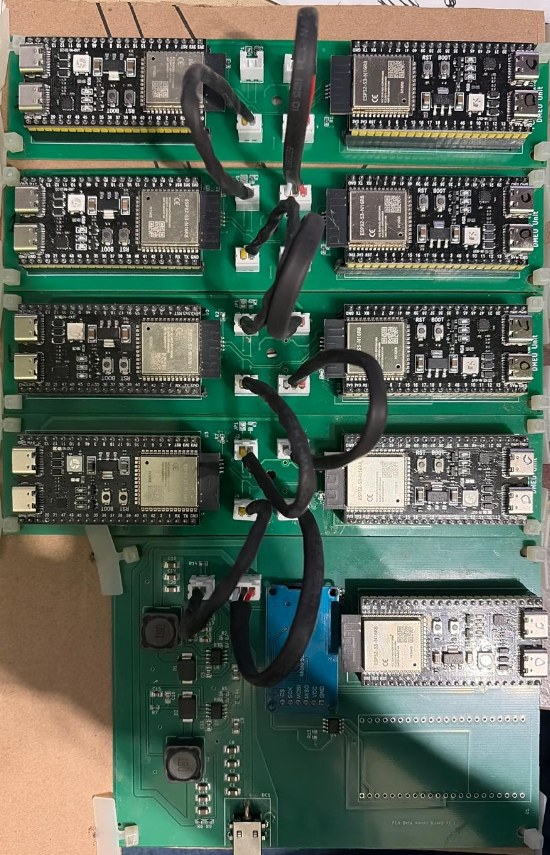
From here it's been careful, methodical iteration: adding features, fixing bugs, learning how to build PCBs of my own, learning how to write websites that use SSE events — something I didn't even know existed three months ago!
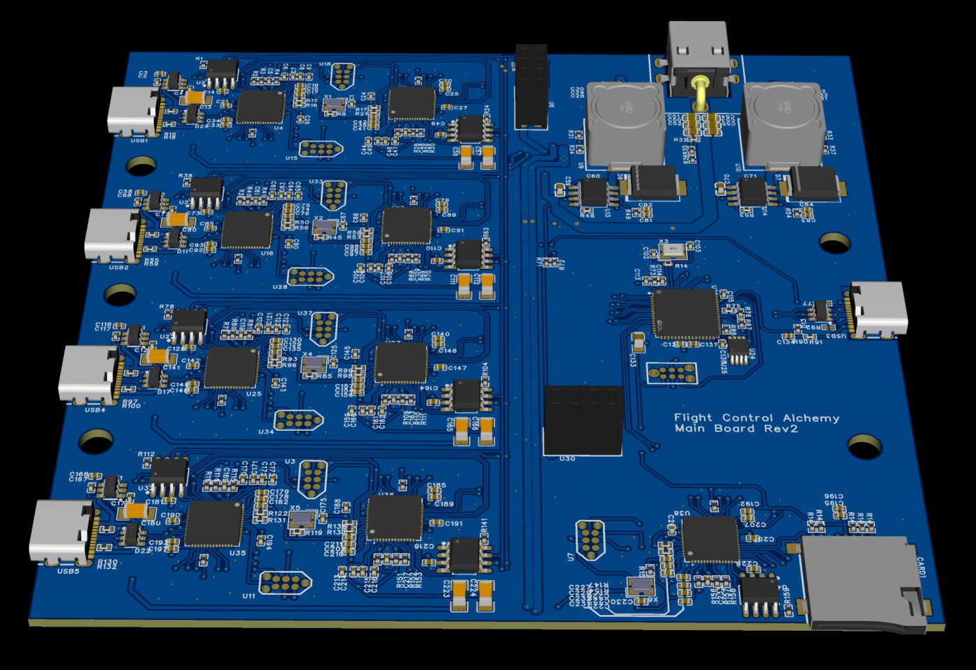
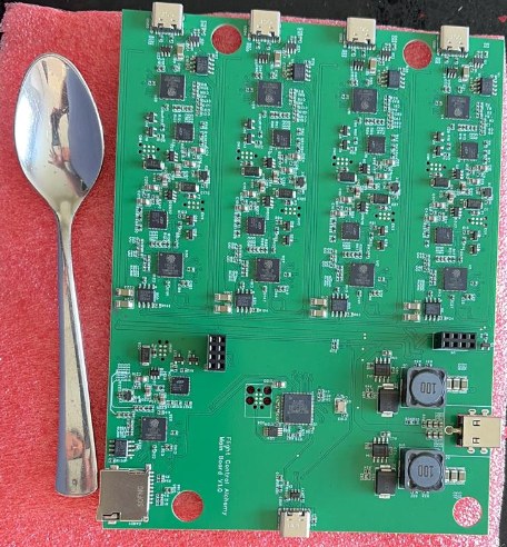
Having got myself to what I'm calling feature-complete, I then set about designing the first production PCB to support up to four units. It includes a power supply, an admin unit, an SD card, and expansion slots for an additional four units — although I have yet to actually add the additional four.
The image below, with a spoon for scale, is that production board — although I'm calling it my lab production board because it has debug headers on it. It's working on my desk right now with four VIRPIL devices connected to it, doing exactly what I ask it to. On a personal note, I can't tell you how good it feels to have thought of an idea and manifested a physical item into the world. The idea, the plan, the design, the electronics, the code — all of it has been done by me, on my own, primarily to solve a problem that I had.
So why post all of this? Well, I'm of the opinion that I can't be the only person who has this problem — or who might find this solution compelling. I have a productionised PCB design that's about 30% smaller again than the one you see here. I've created a website for it, even a name. I'm interested to see what people think, what questions people have, whether there are features I haven't thought of that might be useful — and ultimately to see if people would be interested in spending money on something like this.
The current design uses a random USB VID. One of the main costs, if I ever wanted to turn this into a production item, would be the purchase of a valid production vendor ID for the USB device — a $6,000 one-time cost, so it's not something I can do lightly if I don't know that people are interested.
So let me know your thoughts, comments and questions. What follows is a semi-exhaustive list of what this solution does.
Architecture
- Support for up to 8 input HID devices, up to 500 mA each. (Current units support 4 devices.)
- Support for up to 5 FCA units on the same computer. (No cross-device interaction… yet.)
- Administration over a web UI via a local USB network connection — no drivers or software.
- All power for connected controllers comes from the FCA unit — no draw on the host PC.
- Calculated direct-path latency (e.g. input 1 → output 1) of ~1–2 ms, and cross-device latency of ~10 ms — well under the "motion-to-photon" latency of ~50–100 ms.
Features
- Output devices register with the host with fixed identities to make game mapping reliable even across PCs — e.g. output 1 on FCA 1 = FCA_Device1.1 with a fixed VID/PID/serial number.
- A full mapping engine for axes and buttons, with:
- Axis-to-button
- Axis curves and dead zones, with 2 profiles per axis
- Axis freeze or invert
- Button toggle mode
- Many-to-one and one-to-many mapping — e.g. map a button on the left and right stick to PTT when the game only supports one input (looking at you, CIG 🙂)
- Up to 8 modes with inheritance and LED colour (VIRPIL only so far).
- Output devices provide 128 buttons and 8 axes — e.g. Mode 1 X=X and Y=Y, Mode 2 X=Rx and Y=Ry.
- Cross-device mapping regardless of vendor — virtually push button 1 on your VKB from your VIRPIL, etc.
- A full virtual stick (8 axes, 128 buttons) along with a virtual keyboard and mouse that can be mapped to.
- Save profiles and LED maps (VIRPIL only today) to SD card for sharing, backup and quick game changes.
- Integration with Stream Deck for mode switch, axis freeze, axis-profile toggle and button pushes.
- A documented API for actions like those used on the Stream Deck.